Question:

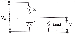
In a Zener regulated power supply circuit as shown in figure below,a Zener diode with Vz=1OV is used for regulation. The load current,Zener current and unregulated input Vin are 5mA,35mA and 20V,respectively. The value of R is:

Updated On: Apr 7, 2025
  • 1000Ω

  • 750Ω

  • 250Ω

  • 100Ω

  • 500Ω

Hide Solution
collegedunia
Verified By Collegedunia

The Correct Option is C

Approach Solution - 1

Given:

  • Zener voltage, \( V_z = 10 \, \text{V} \)
  • Load current, \( I_L = 5 \, \text{mA} \)
  • Zener current, \( I_z = 35 \, \text{mA} \)
  • Unregulated input voltage, \( V_{in} = 20 \, \text{V} \)

Step 1: Calculate Total Current Through Resistor R

The total current through resistor \( R \) is the sum of the load current and Zener current:

\[ I_R = I_L + I_z = 5 \, \text{mA} + 35 \, \text{mA} = 40 \, \text{mA} = 0.04 \, \text{A} \]

Step 2: Determine Voltage Drop Across R

The voltage drop across \( R \) is the difference between the input voltage and the Zener voltage:

\[ V_R = V_{in} - V_z = 20 \, \text{V} - 10 \, \text{V} = 10 \, \text{V} \]

Step 3: Compute Resistance R

Using Ohm's Law:

\[ R = \frac{V_R}{I_R} = \frac{10 \, \text{V}}{0.04 \, \text{A}} = 250 \, \Omega \]

Conclusion:

The value of resistor \( R \) is 250 Ω.

Answer: \(\boxed{C}\)

Was this answer helpful?
1
4
Hide Solution
collegedunia
Verified By Collegedunia

Approach Solution -2

1. Define variables and given information:

  • Vz = 10 V (Zener voltage)
  • IL = 35 mA (Load current)
  • Iz = 5 mA (Zener current)
  • Vin = 20 V (Unregulated input voltage)
  • R = ? (Resistance)

2. Analyze the circuit:

The Zener diode maintains a constant voltage (Vz) across the load. The resistor R limits the current flowing through the Zener diode.

3. Calculate the current through the resistor R:

The current flowing through R (IR) is the sum of the load current (IL) and the Zener current (Iz):

\[I_R = I_L + I_z = 35 \, mA + 5 \, mA = 40 \, mA = 40 \times 10^{-3} \, A\]

4. Calculate the voltage across the resistor R:

The voltage across R (VR) is the difference between the input voltage (Vin) and the Zener voltage (Vz):

\[V_R = V_{in} - V_z = 20 \, V - 10 \, V = 10 \, V\]

5. Apply Ohm's law to find R:

Ohm's law states: \(V = IR\). Therefore:

\[R = \frac{V_R}{I_R} = \frac{10 \, V}{40 \times 10^{-3} \, A} = \frac{10}{40 \times 10^{-3}} = \frac{10^4}{40} = \frac{1000}{4} = 250 \, \Omega\]

Was this answer helpful?
0
0

Top Questions on Semiconductor electronics: materials, devices and simple circuits

View More Questions

Concepts Used:

Temperature Dependence of Resistance

The temperature dependence of resistance is a fundamental property of all materials that conduct electricity. Generally, the resistance of a conductor increases with an increase in temperature. This phenomenon is known as a positive temperature coefficient of resistance.

The reason for this temperature dependence of resistance is related to the interaction of electrons with the crystal lattice of the material. At lower temperatures, the lattice vibrations are minimal, and the electrons are free to move through the material with minimal scattering. This results in a low resistance to the flow of current. However, as the temperature increases, the lattice vibrations increase, causing the electrons to scatter more frequently, which increases resistance.

This phenomenon is governed by the relationship between resistance and temperature known as the temperature coefficient of resistance. The temperature coefficient of resistance is defined as the rate at which resistance changes with respect to temperature. The temperature coefficient of resistance is positive for most metals and semiconductors, meaning that resistance increases with increasing temperature.

However, there are a few materials, such as carbon and certain semiconductors, which exhibit a negative temperature coefficient of resistance. In these materials, the resistance decreases as the temperature increases.

The temperature dependence of resistance has important practical implications in the design and operation of electrical circuits and devices. For example, it is essential to consider the effect of temperature on the resistance of electronic components to ensure reliable and efficient operation of devices over a range of temperatures.