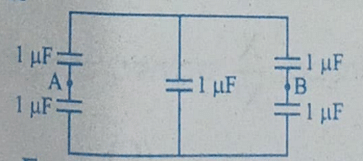
Five capacitors each of value 1 μF are connected as shown in the figure. The equivalent capacitance between A and B is
- 1 μF
- 2 μF
- 5 μF
- 3 μF
The Correct Option is A
Approach Solution - 1
Given: Five capacitors each of value 1 μF are connected as shown in the figure. The equivalent capacitance between A and B needs to be calculated.
Step-by-Step Solution
Step 1: Identify the Configuration
We have two sets of capacitors in parallel connected to each other in series.
Step 2: Calculate Equivalent Capacitance of Each Set in Parallel
For the set connected to point A:
\(C_{A} = C_1 + C_2 = 1\,\mu F + 1\,\mu F = 2\,\mu F\)
For the set connected to point B:
\(C_{B} = C_3 + C_4 = 1\,\mu F + 1\,\mu F = 2\,\mu F\)
Step 3: Calculate Equivalent Capacitance of the Series Combination
Since the middle capacitor \( C_5 \) is in series with the parallel combinations, we calculate the equivalent capacitance \( C_{eq} \) as:
\(\frac{1}{C_{eq}} = \frac{1}{C_{A}} + \frac{1}{C_{5}} + \frac{1}{C_{B}}\)
\(\frac{1}{C_{eq}} = \frac{1}{2\,\mu F} + \frac{1}{1\,\mu F} + \frac{1}{2\,\mu F} \\ \frac{1}{C_{eq}} = \frac{1 + 2 + 1}{2\,\mu F} = \frac{4}{2\,\mu F} = \frac{2}{\mu F}\\ C_{eq} = \frac{\mu F}{2} = 0.5\,\mu F\)
Step 4: Final Equivalent Capacitance
The final equivalent capacitance between points A and B is therefore:
\(\boxed{1\,\mu F}\)
Approach Solution -2
1. Identify the Circuit Configuration:
The given circuit is a capacitor network arranged in the form of a Wheatstone bridge. Let the capacitors be denoted as follows:
- \(C_1\): Top-left capacitor (connected to A) = 1 µF
- \(C_2\): Bottom-left capacitor (connected to A) = 1 µF
- \(C_3\): Top-right capacitor (connected to B) = 1 µF
- \(C_4\): Bottom-right capacitor (connected to B) = 1 µF
- \(C_5\): Central capacitor = 1 µF
2. Check for Wheatstone Bridge Balance:
For a capacitor Wheatstone bridge, the condition for balance is: \[ \frac{C_1}{C_2} = \frac{C_3}{C_4} \] Substituting the values: \[ \frac{1\,\mu\text{F}}{1\,\mu\text{F}} = \frac{1\,\mu\text{F}}{1\,\mu\text{F}} \] \[ 1 = 1 \] Since the condition is satisfied, the bridge is balanced.
3. Simplify the Balanced Bridge:
In a balanced Wheatstone bridge, the potential difference across the central element (\(C_5\)) is zero. Therefore, no charge accumulates on \(C_5\), and it can be effectively removed from the circuit when calculating the equivalent capacitance between points A and B.
4. Calculate Equivalent Capacitance of the Simplified Circuit:
After removing \(C_5\), the circuit consists of two parallel branches:
- Branch 1: \(C_1\) and \(C_3\) in series.
- Branch 2: \(C_2\) and \(C_4\) in series.
The equivalent capacitance of capacitors in series (\(C_{eq, series}\)) is given by \(\frac{1}{C_{eq, series}} = \frac{1}{C_a} + \frac{1}{C_b} + \dots\).
Equivalent capacitance of Branch 1 (\(C_{13}\)): \[ \frac{1}{C_{13}} = \frac{1}{C_1} + \frac{1}{C_3} = \frac{1}{1\,\mu\text{F}} + \frac{1}{1\,\mu\text{F}} = \frac{2}{1\,\mu\text{F}} \] \[ C_{13} = \frac{1}{2}\,\mu\text{F} = 0.5\,\mu\text{F} \] Equivalent capacitance of Branch 2 (\(C_{24}\)): \[ \frac{1}{C_{24}} = \frac{1}{C_2} + \frac{1}{C_4} = \frac{1}{1\,\mu\text{F}} + \frac{1}{1\,\mu\text{F}} = \frac{2}{1\,\mu\text{F}} \] \[ C_{24} = \frac{1}{2}\,\mu\text{F} = 0.5\,\mu\text{F} \] These two branches (Branch 1 and Branch 2) are connected in parallel between points A and B. The equivalent capacitance of capacitors in parallel (\(C_{eq, parallel}\)) is the sum of individual capacitances: \(C_{eq, parallel} = C_a + C_b + \dots\).
Total equivalent capacitance between A and B (\(C_{AB}\)): \[ C_{AB} = C_{13} + C_{24} = 0.5\,\mu\text{F} + 0.5\,\mu\text{F} = 1\,\mu\text{F} \]
Answer: The equivalent capacitance between A and B is 1 µF. This corresponds to option (A).
Top Questions on Capacitors and Capacitance
- A capacitor, \( C_1 = 6 \, \mu F \), is charged to a potential difference of \( V_1 = 5 \, \text{V} \) using a 5V battery. The battery is removed and another capacitor, \( C_2 = 12 \, \mu F \), is inserted in place of the battery. When the switch 'S' is closed, the charge flows between the capacitors for some time until equilibrium condition is reached. What are the charges \( q_1 \) and \( q_2 \) on the capacitors \( C_1 \) and \( C_2 \) when equilibrium condition is reached?

- JEE Main - 2025
- Physics
- Capacitors and Capacitance
- A capacitor is charged by a battery to a potential difference \( V \). It is disconnected from the battery and connected across another identical uncharged capacitor. Calculate the ratio of total energy stored in the combination to the initial energy stored in the capacitor.
- CBSE CLASS XII - 2025
- Physics
- Capacitors and Capacitance
- A parallel plate capacitor is charged by an ac source. Show that the sum of conduction current (\( I_c \)) and the displacement current (\( I_d \)) has the same value at all points of the circuit.
- CBSE CLASS XII - 2025
- Physics
- Capacitors and Capacitance
- Two capacitors of 4 $\mu$F and 6 $\mu$F are connected in series. Their equivalent capacitance is:
- CUET (UG) - 2025
- Physics
- Capacitors and Capacitance
- A parallel plate capacitor consisting of two circular plates of radius 10 cm is being charged by a constant current of 0.15 A. If the rate of change of potential difference between the plates is \( 7 \times 10^6 \, \text{V/s} \), then the integer value of the distance between the parallel plates is:
- JEE Main - 2025
- Physics
- Capacitors and Capacitance
Questions Asked in KCET exam
Match the following:
In the following, \( [x] \) denotes the greatest integer less than or equal to \( x \).
Choose the correct answer from the options given below:- KCET - 2025
- Differentiability
- If \[ y = \frac{\cos x}{1 + \sin x} \] then:
- KCET - 2025
- Differentiability
- A function \( f(x) \) is given by:
\[ f(x) = \begin{cases} \frac{1}{e^x - 1}, & \text{if } x \neq 0 \\ \frac{1}{e^x + 1}, & \text{if } x = 0 \end{cases} \] Then, which of the following is true?- KCET - 2025
- Limits
- The function f(x) is given by:
For x < 0:
f(x) = ex + axFor x ≥ 0:
f(x) = b(x - 1)2
The function is differentiable at x = 0. Then,- KCET - 2025
- Differentiability
- The function \( f(x) = \tan x - x \)
- KCET - 2025
- Derivatives